FAQs
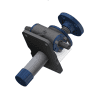
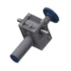
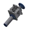
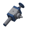
What are the advantages of a MINI?
- Fully made of stainless steel
- Protection rating up to IP65
- Very compact due to hollow shaft motor
Can I attach my own motor to the cylinder?
No, the MINI and linear cylinders are complete systems and cannot be expanded with other motors.
How fast can a linear chain move?
In standard applications, linear drives can be operated with a speed of 250mm/s. Special applications have already been implemented with speeds exceeding 800mm/s.
How does the force-dependent shutdown work with the MINI?
Through a spring assembly, a defined force can be combined via the spring constant. When the spring assembly is compressed, a limit switch sends back the signal. Advantage: The limit switch can also be adjusted in position, allowing the customer to precisely adjust their force point.
Can multiple linear drives be connected together simultaneously?
Yes, linear drive systems with multiple chains connected together are common.
Can linear chains be used in the food industry?
Yes, depending on the proximity to the product, the chain can also be completely made of stainless steel.
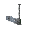
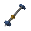
What's a screw jack?
A spindle lifting drive is a combination of a spindle (screw) and a nut (worm gear or traveling nut) that converts rotational motion into linear motion through a worm gear drive.
What sizes of a MINI are available?
MINI 0 (1,000 N), MINI 01 (1,600 N), MINI 1 (3,500 N), MINI 2 (14,000 N), MINI 3 (26,000 N)
What's the difference between the basic version and the travelling nut version?
Basic Version: The spindle itself performs the axial movement.
Traveling Nut Version: The spindle remains stationary in space but rotates. The nut then moves up and down on the spindle.
What are the main/general differences between cubic, classic, HMC, KH?
- Cubic & Classic: primarily external differences. A matter of personal preference regarding which one is preferred. Performance data is nearly identical.
- HMC: Standard up to 3000 rpm input speed, with oil filling and cooling fins - explicitly higher dynamic load capacity.
- KH: explicitly high dynamic capability, but load capacity decreases to a maximum of 90 kN.
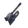
What's the difference between the Linear Chain SK and the Tower Chain TC?
The chain of the Linear Chain consists of links that rest on the shoulders and pins of the succeeding link. The chain of the Tower Chain is constructed with U-shaped chain links, providing greater stability and enabling unguided strokes of over 4m.
What's the efficiency of worm gear drives?
- Standard gearboxes with standard trapezoidal threads achieve efficiencies between 25-35%.
- Increasing the pitch makes the thread slip more easily, thus increasing efficiency.
- The combination with a ball screw can also achieve an efficiency of up to 50%.
- Best combination: bevel gear lifting drives with ball screws, which achieve over 80%.
How can one best implement a position query for a screw jack?
For continuous monitoring, rotary encoders can be mounted on the motor or the worm shaft.
If only the end positions are relevant, limit switches can be used to query the desired end positions.
In hydraulic cylinders, we also often use potentiometers, which then return a certain resistance value that can be read out by the controller.
What are the distinguishing features of high-performance screw jacks?
High-performance screw jacks are designed for demanding applications, providing high durability, precision, and efficiency in industrial environments.
What are the benefits of high-performance screw jacks?
They enable heavy loads, high speeds, and precise positioning. The robust construction ensures long life under extreme conditions.
In which industries are high-performance screw jacks used?
These gears are used in automation, mechanical engineering, robotics, and other industrial sectors where high performance and reliability are required.
What's a high-speed screw jack?
A high-speed screw jack is a mechanical device that enables fast and precise linear motion. It is often used in applications with short strokes and high speeds.
What distinguishes the speed of high-speed actuators?
High-speed actuators are renowned for their rapid speed and ability to perform quick linear movements with short strokes, making them ideal for specific industrial applications.
Which applications benefit from high-speed actuators?
They are utilized in areas such as automation technology, packaging industry, and production lines where fast and precise movements are necessary.
How is the maintenance of high-speed actuators performed?
Maintenance involves regular lubrication according to manufacturer specifications. Inspections for wear and timely re-lubrication are crucial for longevity.
How can the polygon effect in chain systems be prevented?
Since the chain undergoes radial movement due to the polygon effect, the guide plates are extended, and minimal play is allowed. This helps mitigate this effect.
Does a linear chain always need to be guided?
No, within the buckling range, linear chains can also be used without guidance.
What connection options are available for linear chains?
We always recommend using our standard link to connect your load. Utilize all the holes to ensure proper loading of the chain. Dimensions for the front link can be found here: General Catalog
What braking voltage do I need for the MINI?
You can choose between 24V, 230V, and 400V.
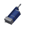
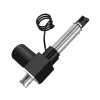
What's an Electric Cylinder?
An electric cylinder is an electromechanical actuator that operates linearly and is powered by electrical energy to generate motion.
How does an electric cylinder work?
An electric cylinder converts electrical energy into linear motion. This is achieved through a motor driving a spindle, which in turn moves a load.
What are the advantages of an electric cylinder compared to other actuators?
Electric cylinders offer precise positioning, easy control, high efficiency, low maintenance requirements, and a wide range of applications.
What are typical features of a high-quality electric cylinder?
Features include high load capacity, precise positioning, robust construction, efficient energy conversion, and a variety of configuration options.
What applications are suitable for electric cylinders?
Electric cylinders are used in various industries, from industrial automation systems to medical and laboratory equipment, as well as in furniture and vehicles.
What does the IP66 protection class mean for actuators?
The IP66 classification indicates that the actuator is dust-tight and protected against strong jets of water. Ideal for applications requiring robust protection.
In what environments are actuators with IP66 useful?
Actuators with IP66 are suitable for harsh environments such as industrial settings, outdoor use, or applications requiring water cleaning.
Do actuators with IP66 require additional maintenance?
The IP66 protection class significantly reduces the ingress of dust and water, minimizing maintenance requirements. However, regular inspection is advisable.
What is the maximum speed of trapezoidal screw drives?
6 m/min
Why is the speed of trapezoidal screw drives limited?
The maximum speed of trapezoidal screw drives is limited by the sliding velocity. If this is too high, the lubricating film tears off.
What's a screw drive?
A screw drive is a mechanical device that converts rotational motion into linear motion. It consists of a spindle and a nut with matching threads.
What types of screw drives are there?
There are various types, including trapezoidal threads, ball screws, and acme threads. Each type has specific applications and characteristics.
What's the difference between static and dynamic self-locking?
Both terms describe the ability of a spindle not to "slip" on its own when at a standstill.
Static self-locking refers to a thread angle between 2.4°-4.5°. In standstill, the spindle does not slip on its own, but it might not come to a stop on its own from motion. Dynamic self-locking occurs when there is an additional braking action from the dynamics. The thread angle is then smaller than 2.4°.
What is a rotation prevention needed for, or when is it necessary?
A rotation prevention is always necessary. Due to the sliding friction in the thread, the applied load would simply rotate along with it, and there would be no relative motion (linear motion).
The higher the axial force on the thread, the higher the frictional force, as Fr = FN * µ.
What does "self-locking" mean?
Self-locking refers to the "non-slip" behavior of spindle-nut systems without external force. The degree of self-locking is influenced by the material pairing, the pitch angle, and the lubrication.
What's the difference between a rotation prevention and a spindle travel limiter?
The confusion sometimes arises because in both cases, there's an additional element at the back of the spindle.
- The spindle travel limiter is merely a ring on the thread that prevents the spindle from falling out.
- The rotation prevention additionally prevents the spindle from twisting.
How can the rotation prevention be implemented?
Customer side: The customer bears the load, preventing it from twisting. If the spindle is then attached to the load, it also cannot twist.
Gear side (product itself has a prevention rotation): We either use a groove running completely through the spindle with a corresponding key as a counterpart. Alternatively, a square block can be screwed onto the back of the spindle, and the protective tube is designed as a square tube.
Can screw jacks also be operated with a duty cycle above 20%?
The specification '20% duty cycle per hour' is always associated with a certain power consumption at the gear unit. Therefore, if the permissible power value is not exceeded, less heat is generated, and the gear unit requires less time to cool down. This allows achieving more than 20% duty cycle.
Can screw jacks units also be used in the food industry?
Yes, screw jacks can be manufactured entirely in stainless steel and equipped with food-grade grease approved according to H1 standards.
What materials are used in screw jacks?
The housing is made of aluminum die-casting or gray cast iron, the spindle, protective tube, and worm shaft are made of steel, while the worm wheel or travelling nut are made of a bronze alloy. Additionally, there are many variants.
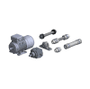
Can I attach my own motor to the screw jack?
Yes, with motor adaptors, motors or geared motors can be flexibly attached. You decide whether you want to provide the motor yourself or if GROB takes care of it.
Can a screw jack also be adjusted with a handwheel?
Yes. A lifting gear unit can be operated with any rotary drive, whether electric, mechanical, or manual.
What does the maximum stroke length of spindle gear units depend on?
When under compression, typically buckling is the limiting factor. Under tension, it's either the availability of raw material (rods commonly available up to 6m) or the critical bending speed (in the case of the travelling nut version). For larger strokes, the spindle can also be made in multiple parts.
Why are motors with dual brakes used?
In applications with high safety requirements, two independently acting holding mechanisms may be required. This could be dynamic self-locking + motor brake or, alternatively, an independently switchable dual brake on the three-phase motor.
Can a three-phase brake motor also be equipped with a 24V brake?
Yes. Common voltage types are 24 VDC / 230 VAC / 400 VAC. Additional voltages in both direct and alternating current ranges are available upon request.
How fast does a three-phase motor rotate?
A three-phase motor rotates depending on the mains frequency. The higher the frequency, the faster the motor rotates. Rated speeds at 50 Hz are as follows: for 2-pole motors, 3000 rpm; for 4-pole, 1500 rpm; for 6-pole, 1000 rpm; for 8-pole, 750 rpm.
What lubricants can be used for screw jacks?
Lubricating grease of NLGI grade 1 or 2, suitable for heavily loaded sliding and rolling bearings. Compatibility with the existing lubricant must be ensured. It's crucial whether the grease is mineral or synthetic-based.
When should the screw jack be re-lubricated?
It depends on the operating cycle and conditions. Typically, every 500 double strokes.
How much lubricant does a screw jack require?
The lubricant quantity depends on the size and type of the gear unit. You can find specific data in our general catalog. Here's an example for our cubic screw jacks: General Catalog 2023 (grob-antriebstechnik.de)
What stroke lengths are available for a screw jack?
0 - 6000 mm in the standard range. Lengths over 6 m are also possible for special applications, but then with a multi-part spindle. Gradations can be made in the millimeter range.
What rotational speed can a screw jack be operated at?
Grease lubrication in the gearbox: up to 1500 rpm; >1500 rpm to 3000 rpm flow grease or oil lubrication.
What limit switches can be installed on a screw jack?
You can install mechanical, magnetic, or inductive limit switch solutions. Preparation for custom sensors is also possible. Please note that it's not possible to implement end position detection on travelling nut version screw jacks.
What loads can a screw jack lift?
For detailed information, refer to the beginning of each screw jack chapter in our catalog. Here's an example for cubic screw jacks: General Catalog 2023 (grob-antriebstechnik.de)
In what mounting position can a screw jack operate?
For grease-lubricated screw jacks, the mounting position can be freely chosen. For oil-lubricated screw jacks, the orientation of the ventilation must be considered.
Can a screw jack be overloaded?
The manufacturer's rated load capacity should not be exceeded. However, screw jacks typically have safety factors ranging from 1.5 to 2.5 times the rated load.
Can a screw jack be operated in the overload range?
Temporarily possible, however, this results in a significantly reduced lifespan.
Can the lifespan of screw jacks be calculated?
Yes, for screw jacks with ball or roller screw mechanisms, a lifespan can be calculated. However, for trapezoidal screw mechanisms, lifespan calculation is not possible. More information on the calculations can be found here.
What power is a screw jack operated with?
The required power depends on the load and lifting speed. A 30% reserve to the required power is recommended for the drive. The screw jack should be operated within the maximum specified parameters, which depend on the version and size. You can find exemplary power limits for cubic screw jacks here: General Catalog 2023 (grob-antriebstechnik.de)
How large is the safety margin in screw jacks, and can it be altered?
The safety margin can be increased or reduced. If reduced, it's important to ensure that block drive is always prevented during operation of the system.
What is a block drive?
A block drive describes the execution of the lift against a fixed stop. In this process, the lifting element is 'blocked' by the fixed counterpart.
How can a block drive be avoided?
The driving element, usually a three-phase motor, doesn't stop automatically but needs a signal for shutdown. This signal can be generated through limit switches, encoders, potentiometers, or other displacement-monitoring components.
Can lifting elements withstand a block drive?
Mechanical drives are very sensitive to movement against fixed stops. Depending on the force of the motor, a block drive typically results in damage to the spindle-nut system.
When do you use a ball screw spindles in screw jacks?
Ball screw spindles make sense when:
- The power consumption is too high in combination with trapezoidal screw spindles
- A higher lifting speed is desired
- A higher precision is desired
What axial play is permissible in a screw jack?
The axial play of a trapezoidal screw spindle typically ranges from 0.1 to 0.3 mm. When the axial play reaches 1/4 of the trapezoidal profile, replacement of the trapezoidal screw nut is recommended.
Can a screw jack unit withstand lateral forces?
Although lateral forces significantly reduce the lifespan of screw jacks, there are certain limits within which lateral forces can be absorbed. You can find relevant information here: General Catalog 2023 (grob-antriebstechnik.de)
What is the difference between a standing and a rotating spindle?
The standing spindle creates relative motion through the rotating worm wheel, while the rotating spindle generates relative motion for the travelling nut. The advantages and disadvantages depend on the space constraints of your lifting system.
Are there different gear ratios available for screw jacks?
Yes, each size (regardless of the screw jack type) offers 2x reduction stages (-> Normal and Slow). The exception is bevel gear screw jacks. Here, gear ratios of 1:1, 2:1, and 3:1 are possible.
What is meant by spindle extension?
Spindle extension defines a dimension that provides a certain extra length compared to the standard when in the retracted state. For example: You only need an effective stroke of 100mm, but there's a distance of 400mm to cover between the start of the stroke and the gearbox. Then we extend the spindle by 400mm, so when fully extended, you reach a total of 500mm.
What options for spindle mounting (head variants) are available for spindle drives?
For the spindle end, the standard range offers options including threaded end, articulated head, ball joint head, flange plate, bearing flange plate, and pin. You can find corresponding dimensions in the General Catalog 2023 (grob-antriebstechnik.de)
Is a screw jack suitable for outdoor use?
Yes, appropriate protection can be achieved through painting or the use of stainless materials.
How can one achieve synchronous operation with multiple lifting elements?
- Electronic bridge: If each lifting element of the system is driven by a motor, electronic synchronization can be achieved through encoders.
- Mechanical linkage: More cost-effective and fail-safe are cardan shafts and bevel gearboxes, which can connect all lifting elements of a system together.
Is it possible to replace a hydraulic cylinder with a screw jack?
Yes, the functions of 'lifting' and 'moving' can be performed by any mechanical lifting element.
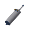
What is meant by a piston tube version?
This version uses an additional tube to protect the spindle, which sits on the travelling nut. The piston tube version thus describes a lifting cylinder that has been modified based on a sscrew jack.
When do I need an oil version, and what information about it is important for the customer?
The following points necessitate an oil version:
- Use in explosive atmospheres with gas. A mandatory ATEX questionnaire is required.
- Input speed at the worm shaft ranging from 1500 rpm to 3000 rpm.
What structural changes are there in the gearbox between ball screw drive and trapezoidal screw drive (outer dimensions)?
In the case of the travelling nut version, only the nut connection dimensions change. In the basic version with the ball screw spindle, it may occur that the bearing cover is raised to accommodate the ball screw nut in the gearbox.
Are there also stainless steel versions available?
Yes, the use of stainless steel materials is a common practice for environments with aggressive media.
How does a safety nut SFM work and when is it useful?
In standard operation, the SFM runs load-free with the main nut. If the main nut fails, the SFM takes over the load. A stroke can then be performed to shut down the system. Additionally, the SFM is also used as a reference nut for wear measurement.
What options are there to protect the gearbox from external dirt?
The spindle can be protected by folding bellows or spiral protective sleeves.
What is the function of a rotation prevention?
It prevents rotation of the spindle. If a translational spindle were to rotate, linear motion would no longer be possible.
What is the function of a travel limiter?
A travel limiter (AS) prevents the spindle from accidentally falling out in the basic version. It is not intended as a mechanical end stop.
Can a linear chain also perform a swiveling movement?
No, swiveling movements are not possible with the linear chain.
Does a linear chain have self-locking capability?
No, you should provide a brake on the motor.
What efficiency do linear chains have?
65% with chain magazine, 80% with free chain.
What is the polygon effect in chain systems?
The polygon effect occurs when a chain is positively driven by a sprocket. In this case, the chain cannot run perfectly circularly on and off the sprocket, causing deviations in the path of the traction medium. The speed of the chain then fluctuates periodically around a mean speed, which can manifest as vibrations in the chain.
Do two linear chains running in opposite directions replace a guide?
No, the load MUST always be guided.
How can the buckling of a linear chain be calculated?
There is no calculation basis for this. The buckling length has been determined through tests. You can find a corresponding diagram for horizontal applications here: General Catalog 2023 (grob-antriebstechnik.de). For vertical applications, please contact us.
Can a push chain be used in a cantilevered manner - without guiding the load?
No, a linear chain can never take over the guiding itself. The load must be guided.
What accessories make sense for push chains?
- Lubrication system: attached lubrication brushes extend the lifespan.
- Chain magazine: the chain can be rolled up behind the housing.
- Reduction gear: especially useful in lifting systems to reduce torque through gears.
- Force sensor: for measuring axial load and protection against overload.
How long is the expected lifespan of linear chains?
Here is no calculation basis for this. Tests have shown that for standard chains, 250,000 cycles, and for hardened chains, 1,000,000 cycles represent realistic values.
How accurately can the linear chain position?
- When under pressure load: depending on the control, 100% repeatability can be achieved.
- Under changing loads: the control system must consider the backlash at the sprocket and manufacturing tolerances in the chain links.
Are there versions of linear chains with increased corrosion protection?
As standard, GROB chains are galvanized. For environments with aggressive media, stainless steel chains can be used.
What temperatures can linear chains withstand?
- Standard: 180°C
- High-temperature continuous: 550°C
- High-temperature short-term (under 2 minutes): 1050°C
What needs to be considered in the dimensioning of linear chains?
- The load must be guided
- The push chain size must be chosen correctly
- It should be driven over a ramp
What needs to be considered in the planning of linear chain systems?
- The load must always be guided
- Acceleration should be controlled via a ramp
- The chain cannot perform a swiveling movement
- The permissible buckling length must not be exceeded
At what speed can a linear chain operate?
Depending on the size, the driving speed is usually below 50 rpm.
Can the chain's lifespan be extended?
Yes, hardened chain links achieve a lifespan four times longer.
What's the difference between a chain magazine and a chain cover?
- A chain magazine winds the chain in multiple circular paths. Advantage: greater space saving.
- A chain cover protects the chain attached to the housing. Due to the attachment, the chain aligns itself and thus halves the stroke length. Advantage: more cost-effective.
Can the chain also be stored in a guide rail?
Yes, the chain can be stored perpendicular to the lifting movement, such as 90°, or even 180° (parallel) to the lifting movement, as in the case of tool tables. The lift then operates on the table, while the storage runs parallel underneath it.
What is the T-guide rail used for?
The T-guide was developed when space for the standard rail above the sliding surface was lacking. In one application example, the customer needed to maneuver with a forklift. The T-guide rail was then embedded in the floor, allowing the vehicles to continue maneuvering undisturbed.
What should I consider regarding the installation positions for linear chains?
The different installation positions do not affect the usability of linear chains (e.g., through oil sight glasses or similar). By simply changing the mounting side of the mounting brackets, the mounting sides can be adjusted as needed.
Can the products also be used in ATEX areas?
Yes, screw jacks and MINI cylinders can be used within certain limits for ATEX zones as well.